The disk brake is the best brake we have found so far. Disk brakes are used to stop everything from cars to locomotives and jumbo jets.
Disk brakes wear longer, are less affected by water, are self adjusting, self cleaning, less prone to grabbing or pulling and stop better than any other system around.
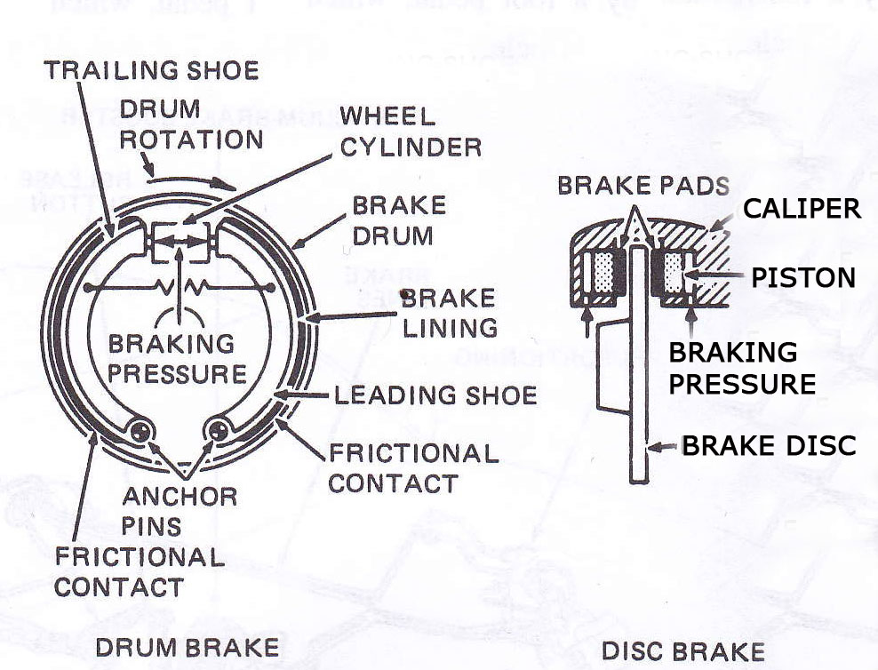
The main components of a disk brake are the Brake Pads, Rotor, Caliper and Caliper Support.
 · Brake Pads
There are two brake pads on each caliper. They are constructed of a metal "shoe" with the lining riveted or bonded to it. The pads are mounted in the caliper, one on each side of the rotor. Brake linings used to be made primarily of asbestos because of its heat absorbing properties and quiet operation; however, due to health risks, asbestos has been outlawed, so new materials are now being used. Brake pads wear out with use and must be replaced periodically. There are many types and qualities of pads available. The differences have to do with brake life (how long the new pads will last) and noise (how quiet they are when you step on the brake). Harder linings tend to last longer and stop better under heavy use but they may produce an irritating squeal when they are applied. Technicians that work on brakes usually have a favorite pad that gives a good compromise that their customers can live with.
Brake pads should be checked for wear periodically. If the lining wears down to the metal brake shoe, then you will have a "Metal-to-Metal" condition where the shoe rubs directly against the rotor causing severe damage and loss of braking efficiency. Some brake pads come with a "brake warning sensor" that will emit a squealing noise when the pads are worn to a point where they should be changed. This noise will usually be heard when your foot is off the brake and disappear when you step on the brake. If you hear this noise, have your brakes checked as soon as possible.
· Rotor
The disk rotor is made of iron with highly machined surfaces where the brake pads contact it. Just as the brake pads wear out over time, the rotor also undergoes some wear, usually in the form of ridges and groves where the brake pad rubs against it. This wear pattern exactly matches the wear pattern of the pads as they seat themselves to the rotor. When the pads are replaced, the rotor must be machined smooth to allow the new pads to have an even contact surface to work with. Only a small amount of material can be machined off of a rotor before it becomes unusable and must be replaced. A minimum thickness measurement is stamped on every rotor and the technician doing the brake job will measure the rotor before and after machining it to make sure it doesn't go below the legal minimum. If a rotor is cut below the minimum, it will not be able to handle the high heat that brakes normally generate. This will cause the brakes to "fade," greatly reducing their effectiveness to a point where you may not be able to stop!
The disk rotor is made of iron with highly machined surfaces where the brake pads contact it. Just as the brake pads wear out over time, the rotor also undergoes some wear, usually in the form of ridges and groves where the brake pad rubs against it. This wear pattern exactly matches the wear pattern of the pads as they seat themselves to the rotor. When the pads are replaced, the rotor must be machined smooth to allow the new pads to have an even contact surface to work with. Only a small amount of material can be machined off of a rotor before it becomes unusable and must be replaced. A minimum thickness measurement is stamped on every rotor and the technician doing the brake job will measure the rotor before and after machining it to make sure it doesn't go below the legal minimum. If a rotor is cut below the minimum, it will not be able to handle the high heat that brakes normally generate. This will cause the brakes to "fade," greatly reducing their effectiveness to a point where you may not be able to stop!
There are two main types of calipers: Floating calipers and fixed calipers. There are other configurations but these are the most popular. Calipers must be rebuilt or replaced if they show signs of leaking brake fluid.
 Single Piston Floating Calipers are the most popular and also least costly to manufacture and service. A floating caliper "floats" or moves in a track in its support so that it can center itself over the rotor. As you apply brake pressure, the hydraulic fluid pushes in two directions. It forces the piston against the inner pad, which in turn pushes against the rotor. It also pushes the caliper in the opposite direction against the outer pad, pressing it against the other side of the rotor. Floating calipers are also available on some vehicles with two pistons mounted on the same side. Two piston floating calipers are found on more expensive cars and can provide an improved braking "feel".
- Four Piston Fixed Calipers are mounted rigidly to the support and are not allowed to move. Instead, there are two pistons on each side that press the pads against the rotor. Four piston calipers have a better feel and are more efficient, but are more expensive to produce and cost more to service. This type of caliper is usually found on more expensive luxury and high performance cars.
· The parking brake (a.k.a. emergency brake) system controls the rear brakes through a series of steel cables that are connected to either a hand lever or a foot pedal. The idea is that the system is fully mechanical and completely bypasses the hydraulic system so that the vehicle can be brought to a stop even if there is a total brake failure.
On drum brakes, the cable pulls on a lever mounted in the rear brake and is directly connected to the brake shoes. this has the effect of bypassing the wheel cylinder and controlling the brakes directly.
Disk brakes on the rear wheels add additional complication for parking brake systems. There are two main designs for adding a mechanical parking brake to rear disk brakes. The first type uses the existing rear wheel caliper and adds a lever attached to a mechanical corkscrew device inside the caliper piston. When the parking brake cable pulls on the lever, this corkscrew device pushes the piston against the pads, thereby bypassing the hydraulic system, to stop the vehicle. This type of system is primarily used with single piston floating calipers, if the caliper is of the four piston fixed type, then that type of system can't be used. The other system uses a complete mechanical drum brake unit mounted inside the rear rotor. The brake shoes on this system are connected to a lever that is pulled by the parking brake cable to activate the brakes. The brake "drum" is actually the inside part of the rear brake rotor.
· On cars with automatic transmissions, the parking brake is rarely used. This can cause a couple of problems. The biggest problem is that the brake cables tend to get corroded and eventually seize up causing the parking brake to become inoperative. By using the parking brake from time to time, the cables stay clean and functional. Another problem comes from the fact that the self adjusting mechanism on certain brake systems uses the parking brake actuation to adjust the brakes. If the parking brake is never used, then the brakes never get adjusted.

· The power brake booster is mounted on the firewall directly behind the master cylinder and, along with the master cylinder, is directly connected with the brake pedal. Its purpose is to amplify the available foot pressure applied to the brake pedal so that the amount of foot pressure required to stop even the largest vehicle is minimal. Power for the booster comes from engine vacuum. The automobile engine produces vacuum as a by-product of normal operation and is freely available for use in powering accessories such as the power brake booster. Vacuum enters the booster through a check valve on the booster. The check valve is connected to the engine with a rubber hose and acts as a one-way valve that allows vacuum to enter the booster but does not let it escape. The booster is an empty shell that is divided into two chambers by a rubber diaphragm. There is a valve in the diaphragm that remains open while your foot is off the brake pedal so that vacuum is allowed to fill both chambers. When you step on the brake pedal, the valve in the diaphragm closes, separating the two chambers and another valve opens to allow air in the chamber on the brake pedal side. This is what provides the power assist. Power boosters are very reliable and cause few problems of their own, however, other things can contribute to a loss of power assist. In order to have power assist, the engine must be running. If the engine stalls or shuts off while you are driving, you will have a small reserve of power assist for two or three pedal applications but, after that, the brakes will be extremely hard to apply and you must put as much pressure as you can to bring the vehicle to a stop.
· The master cylinder is located in the engine compartment on the firewall, directly in front of the driver's seat.

· A typical master cylinder is actually two completely separate master cylinders in one housing, each handling two wheels.
· This way if one side fails, you will still be able to stop the car.
· Master cylinders have become very reliable and rarely malfunction; however, the most common problem that they experience is an internal leak.
· This will cause the brake pedal to slowly sink to the floor when your foot applies steady pressure. Letting go of the pedal and immediately stepping on it again brings the pedal back to normal height.